

How does autoguiding work?
Getting started with PHD Guiding
Push Here, Dummy: your first steps in handling autoguiding software using the PHD Guiding program as an example.
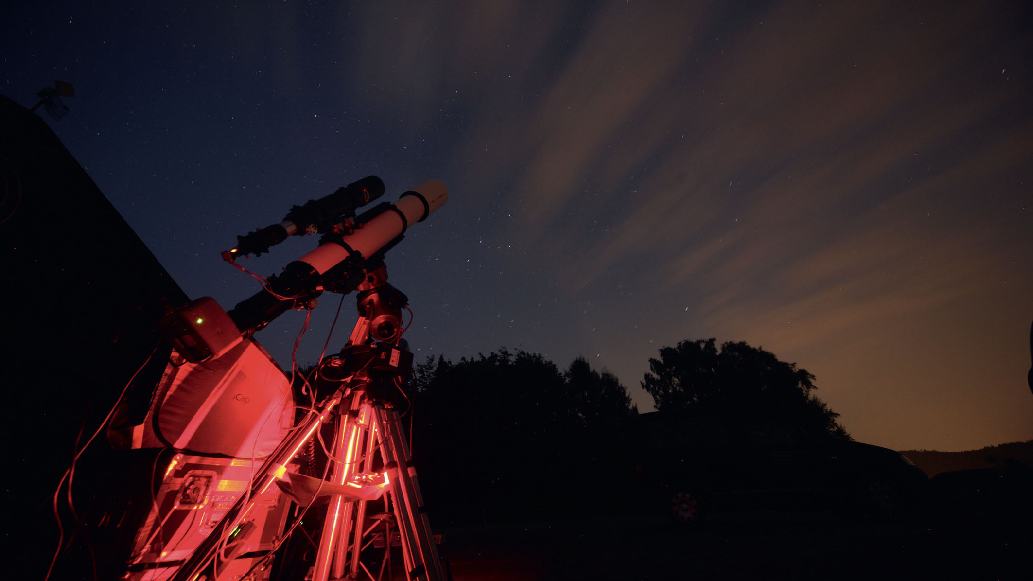 Perfectly-exposed images guaranteed: a telescope with autoguiding equipment in action. Mario Weigand
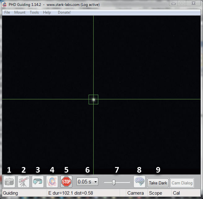 Fig. 2: PHD main window with the important functions. Mario Weigand
This article is about taking your first steps using autoguiding software. The PHD (Push Here, Dummy) Guiding program offers a free solution for this. It claims to be especially easy to use, and it supports virtually all established tracking cameras.
The program is clearly laid out which makes it easy to get going with the subject. Once started, the program window appears: all the basic settings can be reached from the standard menu. Below it you can see the current camera image and lastly the control bar with the most important functions. The program window closes at the bottom with a status bar that shows important messages.
Settings
When using the software for the first time, you will need to set up the necessary connections to the autoguider and to the mount. Here, it is important to decide whether the PC or autoguider is communicating directly with the mount over the ST-4 connector. If this is the case, the option On Camera must be selected in the Mount menu. If you are using a mount without a ST-4 interface, but only with a serial interface (RS-232), then control is managed using the ASCOM driver.
1. Establish a connection
Use buttons 1 and 2 in that order to create a connection to the tracking camera or mount. The corresponding pop-up window will appear in the case of an ASCOM connection.
2. Prepare the autoguider
Once a connection is established, focusing the autoguider is the first step in preparing the system. For this purpose, it may be useful to increase the exposure time to five seconds, so that even defocused stars become visible. Then, in loop mode (button 3), gradually adjust the focus as required. You can mark this position on the focuser which will speed up this process next time.
Exposure times of one second are useful for running the tracking. A suitable guide star must not be too faint, but should also not be overexposed. You can make the selection manually by simply clicking on the desired star. A S/N value is displayed in the status bar to help you evaluate your chosen guide star. It indicates how well the star stands out from the background noise. Values of 4.0 or higher are recommended. If no suitable guide star is available, the field of view can be adjusted using the guidescope rings, an extender, or the off-axis guider.
Once the correct settings have been found, a dark frame with the lens cap on the guiding optic should be taken (button 9) to correct hot pixels. The dark frame is then automatically subtracted from each later image. You’ll need to create a new dark frame if the exposure time is changed. If something goes wrong as you capture the frame, the faulty image can be deleted via the menu Tools/Erase Dark.
3. Calibration
Before you can start the tracking correction, the autoguider needs to be calibrated. This means that PHD Guiding must learn how, and how strongly, the mount responds to the control commands. If the loop mode is still active, it should be stopped now. PHD Guiding starts the calibration process with a click on button 4. Control signals are given to both axes individually, and you can watch how the guide star slowly moves.
The calibration can be optimised for the tracking focal length used by adjusting the Calibration Step parameter in the settings (button 8). For example, 1000ms makes sense for 500mm, and shorter calibration steps of 250ms are advisable for long focal lengths of around 2,000mm.
If the calibration was successful, the program immediately switches to tracking. The status bar will display the message "Guiding" and the star symbol will be green.
4. Autoguiding process and fine tuning
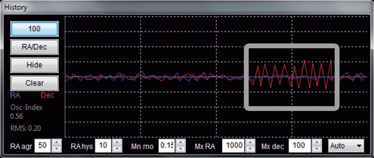 Fig. 3: Typical graph display for smooth tracking. The section on the right shows vibration in the declination axis due to too high aggressiveness settings. Mario Weigand
Tracking performance can be controlled by using the graphical tools available from the Tools/Enable Graph menu. A blue and a red graph represent the deviations in the right ascension and declination axes.
Possible problems:
The program may lose faint guide stars. This is indicated by a yellow star symbol. In this case, only a brighter guide star, a longer exposure time or the Noise Reduction parameter (see below) help.
If the tracking correction does not work correctly, the star drifts away from the target position over time. PHD Guiding indicates this with a red warning message.
A common cause is a faulty cable connection to the mount or excessive backlash.
Furthermore, there are some important parameters, which can be accessed via key 8, which affect the quality of the tracking correction. It must be said that there are no universally correct parameters. The optimal settings must be found for each individual telescope. The following hints can help:
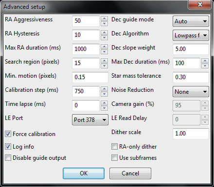 Fig. 4: Advanced settings window. Mario Weigand
RA Aggressiveness:
Aggressiveness is a measure of how strongly the program should react to a tracking error. Use the graphical tool to optimise this. If the aggressiveness is set too low, the guider takes too long to re-centre the guide star after a tracking error. The value should then be increased in increments of ten. If the value is set too high, however, the correction is too great and you will see that the star oscillates around its required position (see Fig. 3). However, you also need to bear in mind the interaction with hysteresis described below!
RA Hysteresis:
Hysteresis is a reaction threshold. The smallest error value for which a correction is to be made can be changed here. If the threshold is set too low, the guiding system reacts to seeing-related fluctuations, which can lead to an over-correction similar to that seen with aggressiveness. This value is also adjustable in increments of ten.
Noise reduction:
If the guide star is faint, pixel binning can help. 2×2 or 3×3 pixels can be combined to improve the S/N value. At the same time, however, resolution is reduced. However, in the case of a guidescope with a very short focal length, the quality of the tracking correction can reduce due to pixel binning. Important: if you change this setting, a new dark frame is necessary! The default settings of the remaining parameters generally don’t need to be changed. Now nothing else can stand in your way for correctly tracked, long-exposed astronomy photos!
Author: Mario Weigand / Licence: Oculum Verlag GmbH